
Most of what an artist needs to know about electronics is very simple.
There may be a lot of little things to play with, but each one is simple.
We'll start with the light emitting diode (we'll call it an LED for short). You put electricity through it, and it lights up.
That seems pretty simple.
Like all simple things, LEDs can seem a lot less simple if you don't know their simple rules.
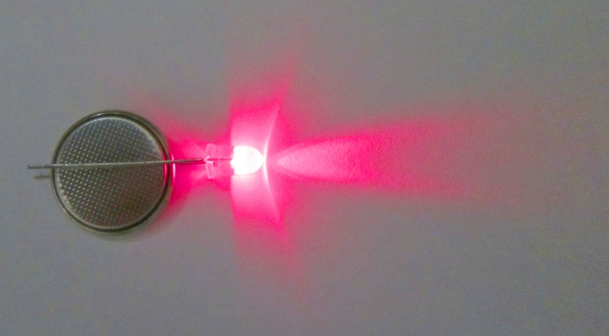
An LED has two wires coming out of it. If you connect one wire to the positive side of a battery, and the other side to the negative side of the battery, you have a 50% chance it will light up. If it doesn't light up, turn it around and it will.
The first rule is the 'diode' part of the name at work: a diode only allows electricity to go through it in one direction.
The tiny little button battery in the photo above is just strong enough to light the LED. What would happen if we connected the LED to the battery in a car, or to a nine-volt battery? That would not be a good idea. At best, the LED would make a little 'pop' sound, and become a dark emitting diode, which we will call a DED.
The second rule of light emitting diodes is that they can only handle a certain amount of electricity.
Electricity is just moving electrons. As electrons move through a conductor such as a wire or an LED, they bump into the atoms in the conductor, causing the conductor to heat up. The temperature rises, but as the temperature becomes higher than that of the surroundings, more of the heat is lost to the environment. So eventually the LED reaches a stable temperature, where the amount of heat generated equals the amount of heat lost.
Each second, some number of electrons move through the LED. If the number of electrons per second goes up, so does the temperature. At some point, the temperature of the LED is so high that the little chip inside the LED breaks, or the tiny little wires that connect to the top of the LED chip simply melt.
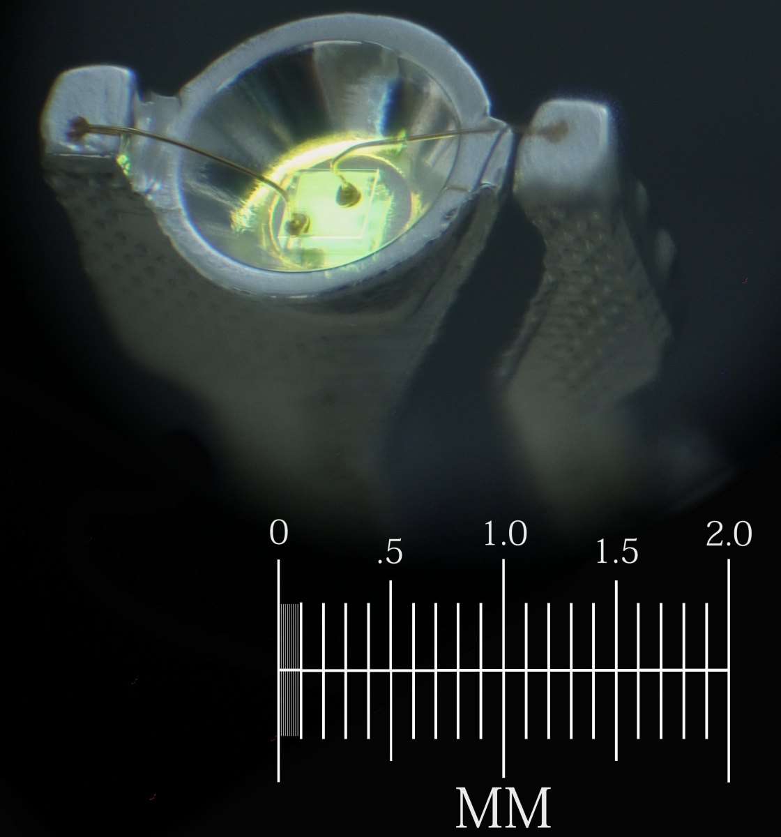
You can see two of those tiny little gold wires in the microphotograph above. A yellow LED chip is glowing inside the little reflector cup. The entire LED is usually encased in a plastic lens, making it very difficult to see. But for this photo, I placed the glowing LED in some oil so that we can see through the plastic easily.
Just as a current of water is measured by how many gallons go by each second, currents of electricity are measured by how many electrons go by each second. We measure electrical current in units called amperes. Our LED can handle about 0.030 amperes (30 milliamperes) before it overheats.
Once we know that, we need to know how to make sure that no more than 30 milliamps goes through the LED. We do that by adding a resistor.
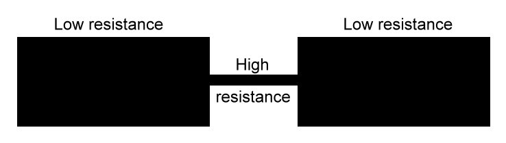
A resistor is a bottleneck for electric current. A resistor can be something as simple as a narrow wire. The thinner the wire, the less electricity can go through it.
We can also make a resistor by using a wire made from something that electrons have a difficult time moving through. Carbon is such a material. It is made up of many little grains, and where the grains touch, the electrons can go from one grain to the next. However, the grains only touch in tiny spots, just like two balls can only touch in one tiny spot when put together. So they restrict the flow of electrons like the thin wire does. Materials like carbon also hold onto their electrons more tightly than copper wire does, so there are fewer electrons available to move.
So now we can try lighting our LED from a nine-volt battery, through a resistor to keep the current below 30 milliamps. But how much resistance do we need?
A nine-volt battery pushes the electrons through the LED three times harder than the three-volt battery did. Voltage is just the pressure on the electrons. If we put more pressure on the electrons, more of them will flow through the resistor, and through the LED in each second.
To figure out how much resistance we need to add, we can measure the current in our circuit while we gradually reduce the resistance, until we get to the value we want.
I picked a few resistors almost at random to try in our circuit. Resistance is measured in ohms, and I picked two resistors with 220 ohms, and one with 1,000 ohms. Resistors have color codes to tell you what values they are, and the two 220-ohm resistors have the colors red, red, brown, and gold. You can memorize the resistor color codes, or you can print them out on paper, or you can just use the multimeter, which can measure the resistance directly.
We are going to use solderless breadboards a lot, since they make building circuits much easier. A solderless breadboard has rows of holes we can poke wires into. The two rows of holes at the edges have all of the holes electrically connected to one another. Each of the more numerous groups of five holes in the middle have all five holes connected to one another. If we put a wire into one of the five holes, and a second wire into another of the same group of five, the two wires will be electrically connected.
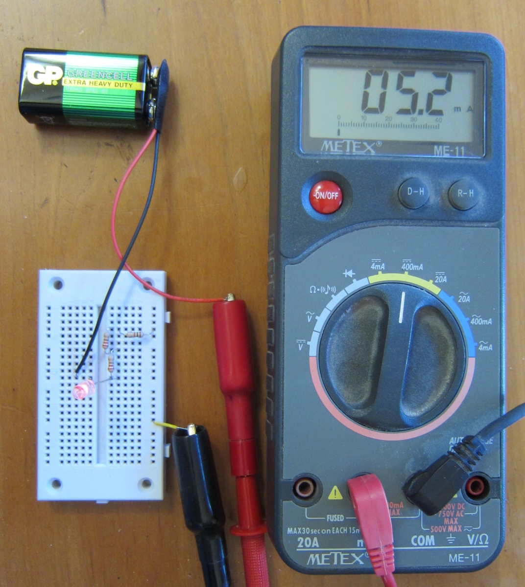
The photo above shows our circuit. The electrons come out of the battery through the black wire. They then go through the LED. From there they go through one 220-ohm resistor, then the other, then the 1,000-ohm resistor, and then into the meter. Finally, they exit the meter and return to the battery. They make the full circle through all the parts and back to the battery. This is why we call it an electric circuit.
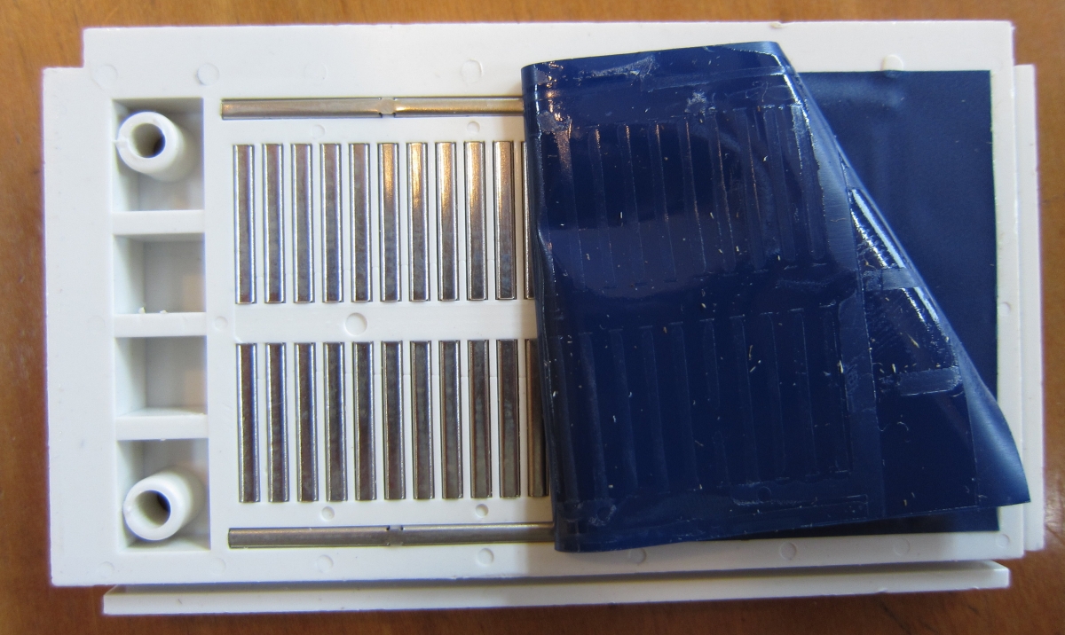
To help you understand how solderless breadboards are constructed, the photo below shows one where I have removed the sticky tape from the back, so you can see the rows and columns of metal connectors joining all the holes. Each connector is a U shaped bit of metal that is springy enough to open up a little when we push the wire into it, and strong enough to hold the wire in place.
Now back to our circuit. The meter is showing that we have 5.2 milliamps flowing through the LED and the resistors. Since we wanted 30 milliamps, we know that we have too much resistance.
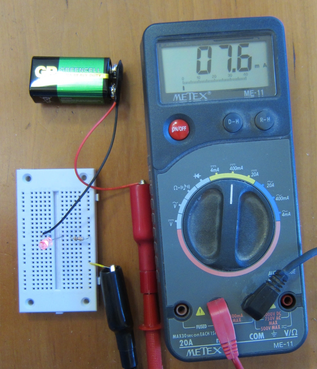
So let's just use the 1,000-ohm resistor. The photo above shows the meter reads 7.6 milliamps. That is closer, but still not the 30 milliamps we want. We want the LED to glow as brightly as it safely can.
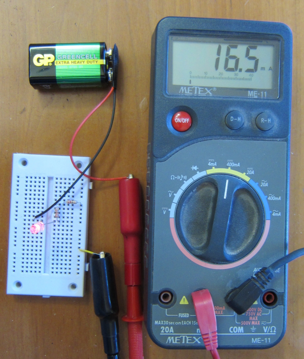
The photo above shows the circuit with just the two 220-ohm resistors (so we have 440 ohms altogether). The meter is showing 16.5 milliamps, more than half of what we are aiming for. What happens if we just use one of the 220-ohm resistors?
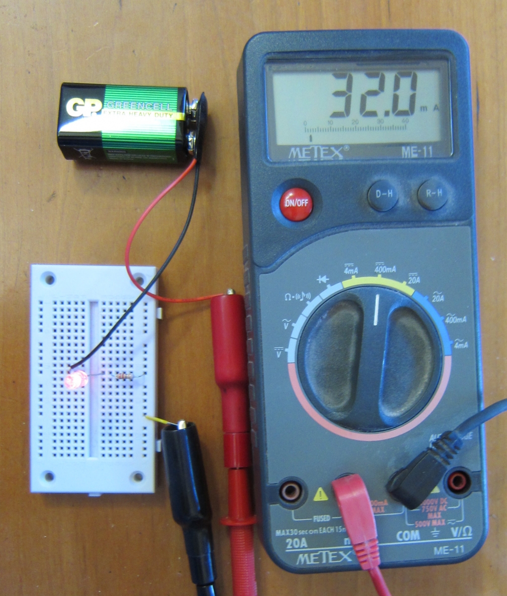
Oops! We overshot the mark. But not by a lot. We are only high by a little less than 7%, and our LED can handle that. No popping noises, no dark emitting diodes. We have a success.
Rather than do all of that resistor swapping and guessing, wouldn't it be nice if we could just plug in the voltage we have, and the current we want, and have a calculator figure out what resistor to use? We can, but to figure out what to enter into the calculator, we need to know a third rule about diodes.
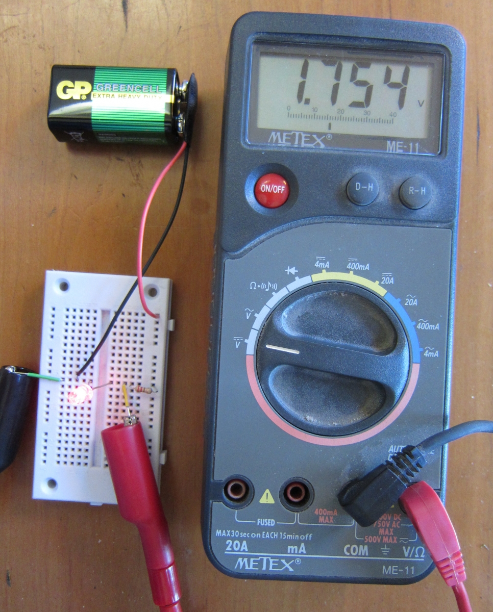
In the photo above, we have connected the meter leads to the leads of the LED in our circuit, and switched the meter to read volts. The meter tells us that the voltage difference between those two spots (the two legs of the diode) is 1.754 volts. Each different kind of diode has a characteristic voltage, called the forward voltage drop. For red LEDs, it is about 1.75 to 1.8. For other colors, it is higher as the colors go through the spectrum. Green LEDs might be 2.3 volts. Blue LEDs are around 3 volts. The voltage drop can be measured, as we just did, or you can read it on the back of the LED package.
Now we have enough information to use a calculator.
The resistance we need is the voltage divided by the current. This is called Ohm's Law, named after the scientist who worked it out.

The voltage is the voltage of the battery, minus the voltage drop of the diode. In our case, the battery voltage is 8.45 volts (we can measure it in our circuit, as I did in the photo above). We subtract 1.754 volts and get a little less than 6.7 volts. If we divide that by 0.030 amperes (the current our LED can handle without overheating), we get 223 ohms.
If you have a computer or a smart phone, Google can help you do the calculation. Google knows that volts divided by amps gives you ohms. Try it:
(8.45 volts - 1.754 volts) / 30 milliamps
In our circuit, we found that we got 32 milliamps from our 220 ohm resistor. We can ask Google to give us the voltage:
32 milliamps * 220 ohms Google says the result is 7.04 volts. But we expected 6.7 volts! What went wrong?
Let's check the resistance with our meter.
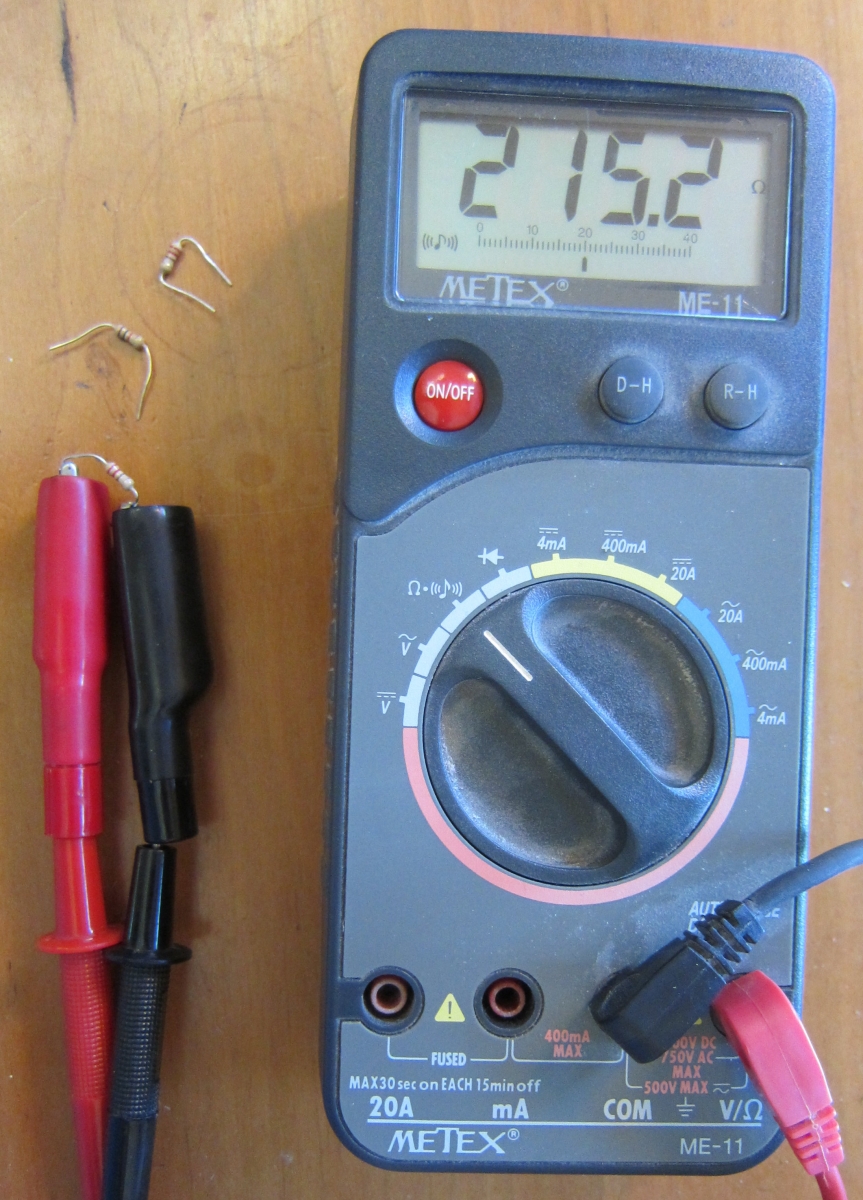
The resistor wasn't actually 220 ohms. It was 215.2 ohms. Let's ask Google again:
32 milliamps * 215.2 ohms Oh good! Now we get 6.8864 volts, which is very close to the 6.7 volts we expected.
The gold band on the resistor tells us that the value is within 5% of the value coded in the color codes. In this case, it is 2.2% off. We will expect a certain amount of sloppiness in our measurements (meters are not perfect, and the connections we make are not perfect), and in our parts values, such as our resistor. And we saw that our LED could handle 32 milliamps instead of the 30 the package told us to limit the current to. When our parts are only specified to 5% accuracy, we can tolerate that much slop in our results.
10 volts / 50 milliamperes is 200 ohms.
2 amperes * 300 ohms is 600 volts.
120 volts / 2000 ohms in milliamperes is 60 milliamperes.
You can memorize these three relations:
- resistance = volts ÷ current.
- voltage = current × resistance.
- current = volts ÷ resistance.
or you can remember one, and do a little algebra to get the other two. Or you can just tell Google to multiply or divide one by another, and if you don't get volts, ohms, or amperes, you change the multiply to a divide or vice-versa. So even if you hate algebra and hate memorizing, you can still work it out.