
 The stars in this elegant custom couture headband actually sparkle. Here's how we make one.
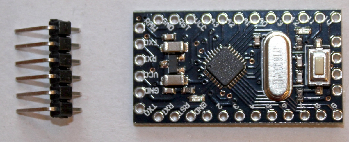 We start with the Arduino Pro Mini. This tiny computer is similar to our current favorite (the Arduino Nano), but it does not have the built-in USB circuit for programming it. Instead, we need to use a device called an FTDI USB-to-Serial converter, attached to the six pins we are going to solder onto the computer in a moment. Why not use the Nano, and get the convenience of the built-in USB? We want to power this project from two tiny 2032 button cells, and the USB circuits consume a lot of power, using up the batteries too fast. But plugging the computer into the FTDI board instead of a USB cable is just as easy -- we just need to move the FTDI board from project to project, or buy several of them if we are programming as a group.
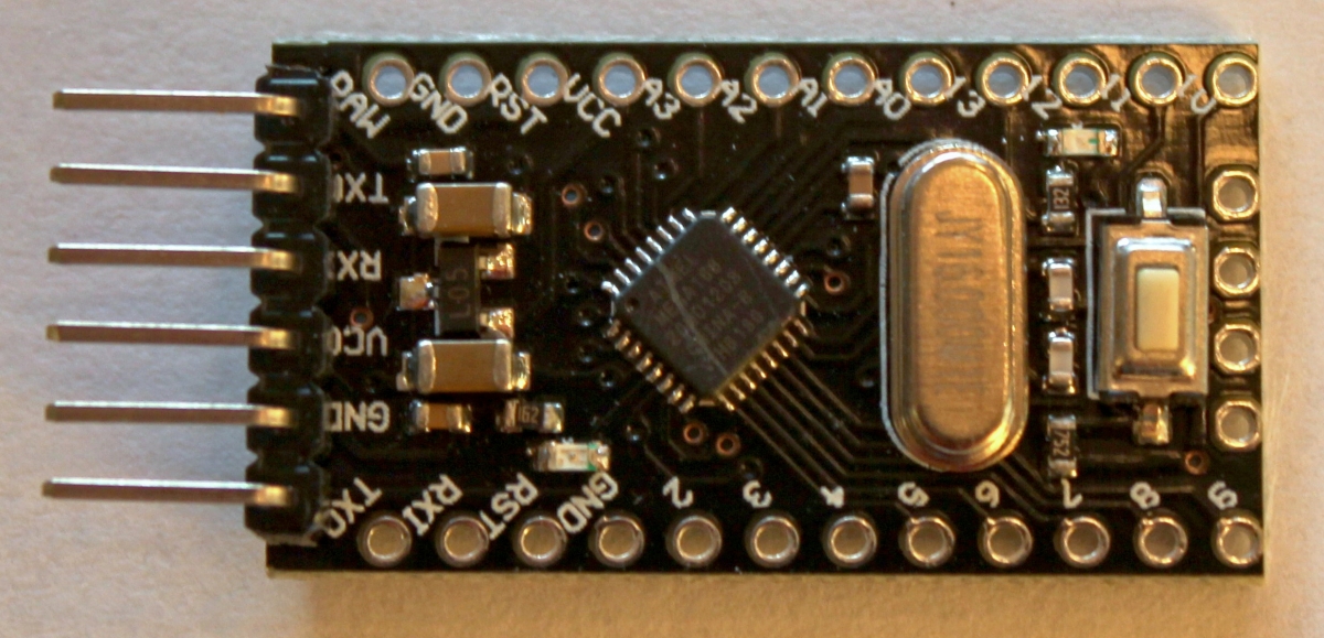 The first step in the construction is to solder those pins to the computer board.
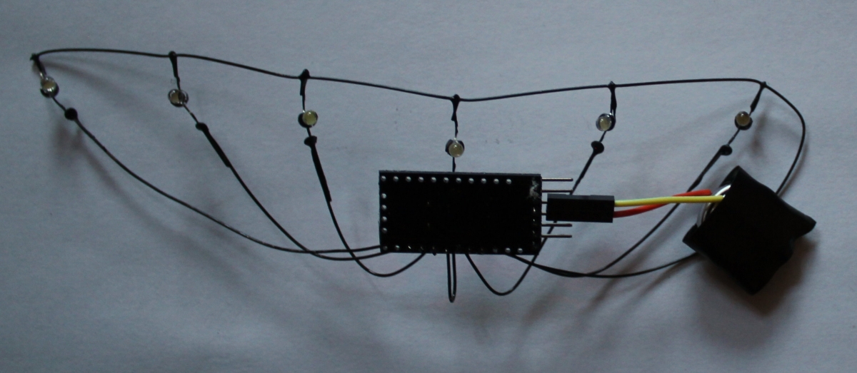
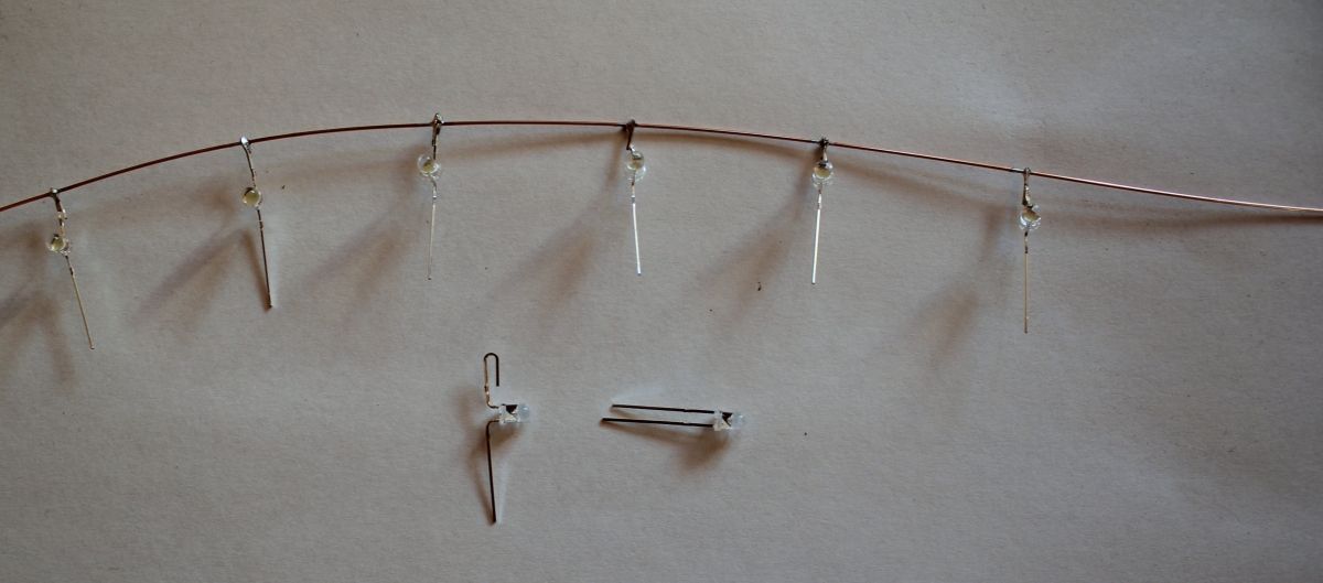 Next, we will solder 6 white LEDs to a long bare copper wire that will be our ground connection.
To make this easier, we bend the leads carefully, so they are doing the splits. Then we fold back the shorter of the two legs (the cathode wire, which will attach to ground) to make a hook. We hook the LED onto the ground wire, and press the hook flat to hold it in place while we solder it to the ground wire.
We space the LEDs an inch apart along the ground wire. The right end of the ground wire is left long, about 6 to 8 inches, since it will have to bend back around to connect to the computer.
 The next step is to cut six bare copper wires about 6 inches long, and form a tiny loop in one end. This loop fits over the long LED leg (the anode) to make soldering it to the anode easier.
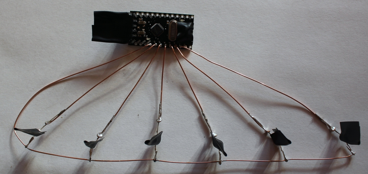
Once all six wires are soldered to the anodes of the LEDs, it is time to connect the computer. The long end of the ground wire is bent down to connect to the ground hole. Feed the wire through the hole from the top, and don't worry (yet) about how far it extends through the hole. We will pull all of the wires in quite a bit in a moment.
The anode wires connect to holes D2 through D7, in order. Pull the wires through the holes, keeping the ground wire straight, so the LEDs are all in a row. When the wires are all pulled tight, bend them over under the computer and solder them to the holes. Finally, trim off the excess wire from the back of the board.
This is a good time to program the computer, before we paint all the wires to insulate them from one another. If anything has been done improperly, it is much easier to fix them unpainted.
The program would be very simple, but we have added some code to make it run much longer from the batteries. Here is the code:
#include "LowPower.h"
#ifdef __AVR__
#include <avr/power.h>
#endif
void
setup( void )
{
DDRD = 0xFC;
DDRB = 0;
PORTB = 0;
power_all_disable();
power_timer0_enable();
}
void
loop( void )
{
LowPower.powerDown( SLEEP_120MS, ADC_OFF, BOD_OFF );
PORTD = DDRD = 1 << (random( 6 ) + 2);
delay( 1 );
PORTD = DDRD = 0;
}
The first four lines just include the header files we need for the low power code.
The setup() function sets the six pins D2 through D7 to be outputs with the single line
DDRD = 0xFC;
The rest of the setup() function is about saving power. We make the rest of the pins (the port B pins) be zero, and inputs, and we disable all of the devices on the computer, except for timer 0, which is needed for the delay() function.
The loop() function first just sleeps for 120 milliseconds in low power mode. This uses very little power, so the batteries last all day.
When it wakes up, we pick an LED at random from the range D2 to D7. That's what this part of the code does:
1 << (random( 6 ) + 2)
This gives us a number to put into both the Data Direction Register for port D (DDRD), and to port D itself (PORTD). The result is that one of the LEDs turns on.
But not for long. In fact, only for a millisecond (that's what the delay(1) does). Then we turn the LED off by setting DDRD and PORTD to zero.
Now we return from the loop function, which is immediately called again, and the program sleeps.
Once the computer has been programmed and all the LEDs are sparkling nicely, it is time to paint those bare copper wires. We use electrical tape to cover the LEDs, the programming pins, and the little reset button, as shown in the photo below:
 We use black epoxy appliance paint to coat the wires. Spray everything on both sides, and let it dry for 10 minutes. Then give everything a second coat, and let it harden for an hour.
 When the paint is nice and dry, we can gently fold the computer up next to the LEDs, to make a more slender arrangement that can slide into the pocket of the headband.
The batteries are simply two 2032 lithium coin cells (button cells). We use electrical tape to attach the bare ends of two connector wires, and to keep the batteries stacked on top of one another, to provide 6 volts. The connector ends of the wires slip onto the ground and VCC (power) pins of the computer. This makes the batteries easy to remove for recharging.