
There is nothing new to learn in this project. It is just a collection of things we have already done.
We built a motor controller using the SN754410 H-bridge chip. We controlled servo motors. We detected distance using sonar. All of those projects come together in Rover, a little robot that scans his surroundings and rolls along avoiding obstacles. This project is based on some very clever designs by Alexander Reben, to which I have added extra goodies (like the sonar scanner) and all the software.
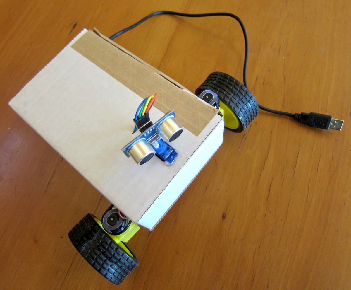
The photo above shows Rover as seen from above. You can see the HC-SR04 sonar sensor is glued to the arm of a small servo motor. The servo can thus rotate the sonar sensor to get an idea of the distances in front of the robot, allowing him to know where obstacles are in front and to the side, and where the wide open spaces are.
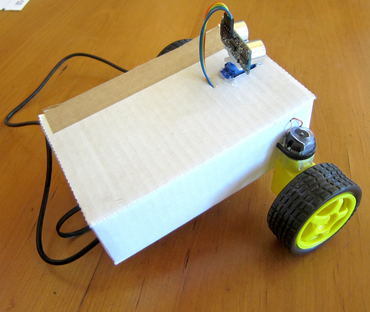
From behind we can see that there are two yellow DC gear motors with wheels, attached to a cardboard box with cable ties. A third cable tie is seen in the back, acting as a rear ski for low friction support. Each of the two motors can move in forward or reverse, allowing the robot to spin left or right in place, or move forwards and back.
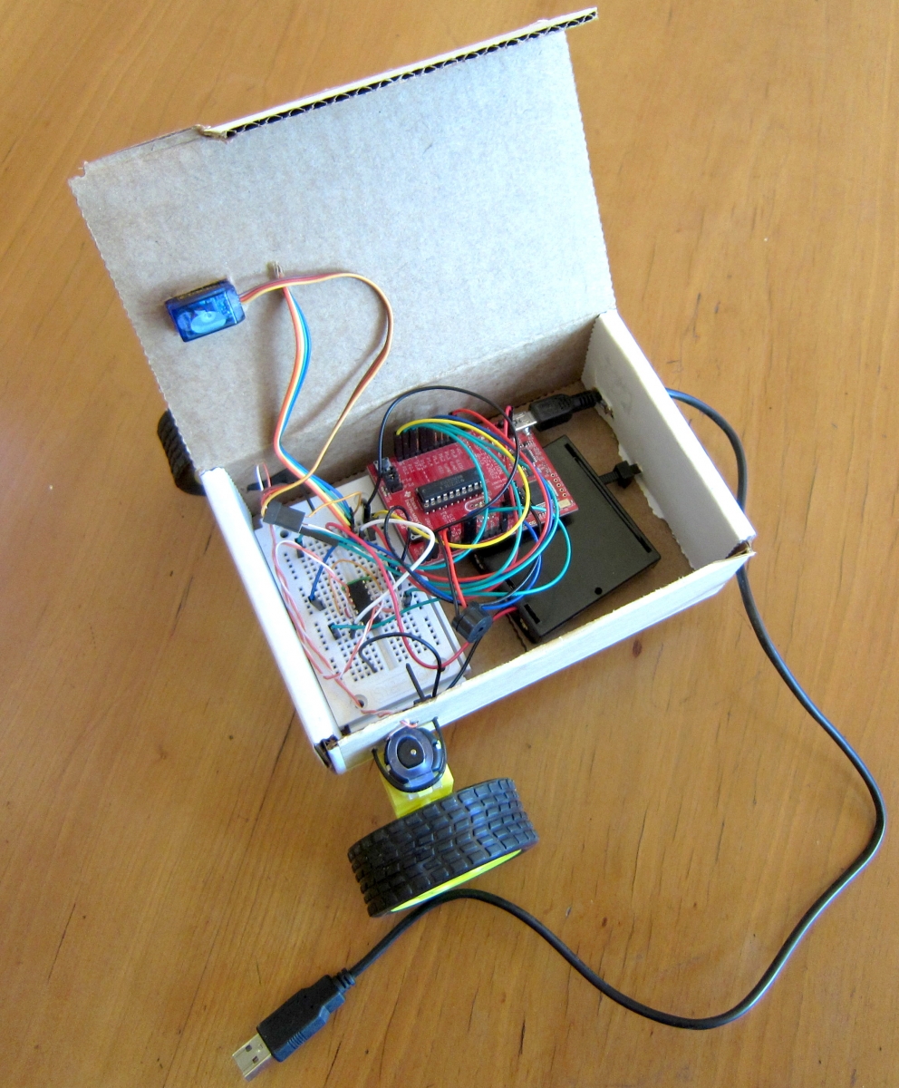
Opening up the lid shows us Rover's insides, a crazy rat's nest of wires, but simple to understand when we look at each function separately.
The black box under the Launchpad holds 4 AA cells, used for power when the robot is not connected to the USB port. That provides 4.5 volts, which is enough to power the sonar sensor and the DC motors. The black ground lead from the batteries is stuck in an empty hole in the solderless breadboard when the robot is not powered up. To turn the robot on, that lead is placed in a hole connected to one of the four ground pins on the SN754410 H-bridge chip. That saves having to buy a switch.
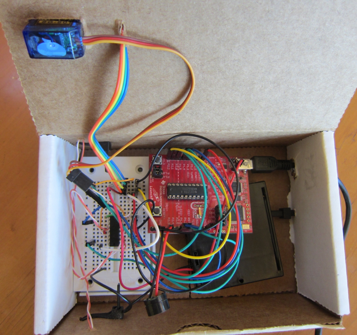
Both sides of the H-bridge chip are used, since we have two motors.
The wheel on the right is connected to the H-bridge so that the Launchpad's P1.2 and P1.4 control whether it is off, moves forward, or moves back. The left wheel is controlled by the Launchpad's P1.6 and P1.7.
The sonar sensor is connected to P2.2 for the trigger, and P2.1 for the echo. The echo has a 1,000 ohm resistor between the sensor and the Launchpad. The sensor is powered from the battery, since it needs 4.5 to 5 volts.
The servo motor is controlled by P2.0. It gets its power from the battery.
A tiny speaker is attached between P2.3 and ground, so the robot can beep.
A clever trick Alexander Reben used is to take the box the Launchpad came in, and carefully turn it inside-out, so the outside is white. This is used for the body of the robot (in the photos above, I actually used a different, but similar box I had lying around).
Some ideas for improvements:
- Mount the batteries on top of the robot, and give them a female USB connector. Then the 'tail' of the robot would plug into the batteries to act as the power switch. Inside the robot, the 5 volt power could come from a wire soldered to the Launchpad's TP1 test point near the USB connector.
- Use the LED Proximity Switch (mounted so it looks down in front of the robot) so the robot can tell if it is about to fall off the table.
- Write more code to control the robot's behavior. You can use the Proximity Switch to let it follow a black line on a white surface, for example, by putting two detector LEDs on either side of the white LED. Now the robot can follow a complicated course that you draw on paper with a black felt pen.
- Replace the motors and servo with quiet stepper motors so the robot can sneak up on people.
Rover, a simple robot