We can make both on-board LEDs flash if we like:
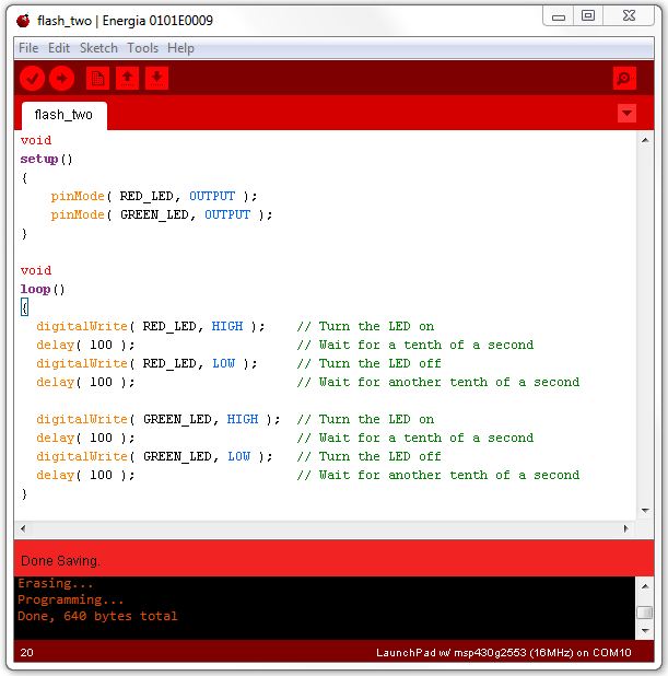
First the red light flashes, then the green, and then it repeats.
If we wanted to control a larger number of LEDs, our program would get rather large. We can trim it down a bit by remembering that the names RED_LED and GREEN_LED are just synonyms for numbers.
If you look carefully at the Launchpad board, you will see that the pins are labeled. One of them is labeled P1.0 (LED1). That tells us that the pin is one of two 'ports' (collections of bits connected to pins) called P1 and P2. Port 1 (P1) has eight bits, and LED1 (the red LED) is connected to the first one, bit zero. You can see the other seven bits on the board, and the eight bits on Port 2 (P2) (Bits 6 and 7 of Port 2 are not labeled -- they are labeled XIN and XOUT). P1.6 has the additional label (LED2), showing us that the second LED (the green one) is connected to that port bit.
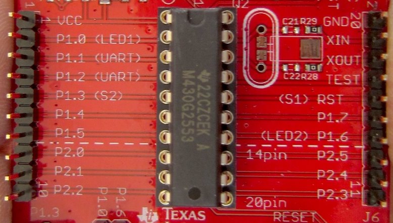
We can write to all of the bits in a port with a single instruction.
Here is a simple program that counts from zero to 255, over and over, on Port 1:
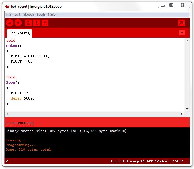
In the setup() function, we make all of the bits output bits. In our earlier programs, we did this one pin at a time, using the
pinMode( RED_LED, OUTPUT );
function. Remember, OUTPUT was a synonym for 1.
In our new program, we set all eight bits on Port 1 to be in the output direction by making a number that has eight binary bits all set to one (that is what B11111111 means -- B is for binary, and there are eight one bits after it). The P1DIR is the name of the place in the Launchpad that controls the direction (INPUT or OUTPUT) of Port 1.
Next, the setup() function sets all eight of the Port 1 output bits to zero. We don't need to say B00000000, because that is the same as zero.
In the loop() function, we add one to whatever number is in P1OUT. P1OUT is zero at first, so after we increment it (that's what the '++' does -- it adds one to something), it will be 1, and the LED connected to Port 1, bit 0 will turn on.
Our Launchpad only has two LEDs on the board. But we can attach jumper wires from the Launchpad to a solderless breadboard, and put eight LEDs there. We run the jumper from each of the P1 port bits to the breadboard, and we also run a jumper from the GND pin to the breadboard, so the circuit will be complete.
Our little computer is so fast, it can count to 255 in less than the blink of an eye. We put a half-second delay in the loop() function so we can see it count. If we didn't, all of the lights would look like they were on at once, even though they are actually flashing millions of times per second.
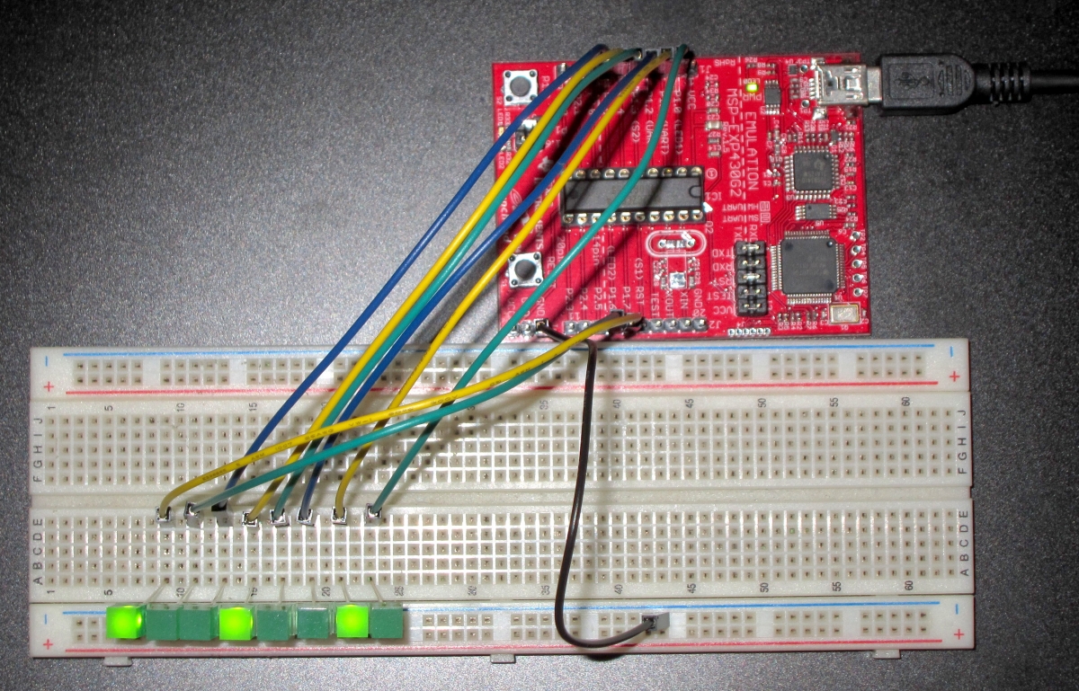
In the photo, you can see we have captured the image just as the Launchpad has counted to the number B10010010, which is the same as the number 146. Each LED represents one power of two. We can see that bit 7, bit 4, and bit 1 are turned on. 27 is 128, 24 is 16, and 21 is 2. Adding them up, we get 128 + 16 + 2, which is 146.
If counting in binary seems tedious, don't worry. The computer will do it all for you.
When programming the Launchpad, sometimes we will be referencing the inputs or outputs by their pin numbers, and sometimes by their Port number and bit number. There are 20 pins on the chip, and 8 of those are connected to Port 1, and another 8 of them are connected to Port 2.
Don't get confused with the two ways to talk about the same wire connected to the LED. Some commands (like pinMode, and digitalWrite) deal with pins, and they number the pins from 1 to 20. This is a holdover from the Arduino system that Energia is emulating on the Launchpad. The Arduino is an older system, and it numbered its ports instead of having nice labels like the Launchpad has. Here is the mapping table to convert Port and Bit numbers to pin numbers:
| Pin 1 | |
| Pin 2 | Port 1 Bit 0 |
| Pin 3 | Port 1 Bit 1 |
| Pin 4 | Port 1 Bit 2 |
| Pin 5 | Port 1 Bit 3 |
| Pin 6 | Port 1 Bit 4 |
| Pin 7 | Port 1 Bit 5 |
| Pin 8 | Port 2 Bit 0 |
| Pin 9 | Port 2 Bit 1 |
| Pin 10 | Port 2 Bit 2 |
| Pin 11 | Port 2 Bit 3 |
| Pin 12 | Port 2 Bit 4 |
| Pin 13 | Port 2 Bit 5 |
| Pin 14 | Port 1 Bit 6 |
| Pin 15 | Port 1 Bit 7 |
| Pin 16 | |
| Pin 17 | |
| Pin 18 | Port 2 Bit 7 |
| Pin 19 | Port 2 Bit 6 |
| Pin 20 |
I suggest you always use the port numbering system (i.e. P1_4 to mean pin 4 on port 1) instead of numbers.
