We explored earlier how to dim an LED using a resistor.
When we put a resistor in series with an LED, the same current flows in the resistor as in the LED.
The current that flows in the LED is useful -- it goes mostly into providing the light we want.
The current that flows in the resistor creates heat. This is a waste of energy if all we want from the circuit is light.
The amount of power lost (dissipated) in the resistor is something we can calculate. The power (in watts) is the current squared, divided by the resistance. Using Ohm's Law, we can restate this in the following ways:
Watts = amperes2 × ohms
Watts = volts × amperes
Watts = volts2 ÷ ohms
In our simple circuit where 6.8864 volts causes 32 milliamperes to flow in both the LED and the 215.2 ohm resistor, we lose:
(0.032 amperes × 0.032 amperes) × 215.2 ohms = 0.2203648 watts
0.032 amperes × 6.8864 volts = 0.2203648 watts
6.8864 volts × 6.8864 volts ÷ 215.2 ohms = 0.2203648 watts
We are losing almost a quarter of a watt in the resistor.
What that means
Suppose we are powering our earlier simple circuit with a 9 volt battery. The battery can supply 0.565 ampere-hours at 9 volts, for a total energy capacity of 5.085 watt hours of energy.
Our circuit draws 32 milliamperes of current, so we would expect the battery to last 17.6562 hours.
During those 17 hours, the resistor is dissipating a quarter watt of power in the form of heat for each of those 17 hours. That's 17.6562 hours * 0.2203648 watts, or 3.89 watt hours of power. That's over three quarters of the power in the battery, wasted as heat in the resistor.
A more efficient circuit
Suppose we replace the resistor with some more LEDs. Each LED drops the voltage by 1.754 volts (see our earlier discussion of this circuit), so five LEDs in series would drop 8.77 volts.
I built the circuit, and here's what I measured. The battery was putting out 9.38 volts. With 5 LEDs in series, the current was 1.71 milliamperes. The five LEDs were dim.
With four LEDs in series, the voltage dropped to 9.27 volts, and the current jumped to 24.7 milliamperes. The LEDs were nicely bright.
Since the amount of light is proportional to the current, we can calculate how much light each circuit produces relative to the other. The LED and resistor had a current of 32 milliamperes. The five LEDs in series had 1.71 × 5 or 8.55 milliamperes producing light. The four LEDs in series had 24.7 × 4 or 98.8 milliamperes producing current. So the four LEDs are producing 3.0875 times as much light as the single LED with its current limiting resistor, while using only 77% as much current (24.7 ÷ 32).
The new circuit can run 22.8744 hours on the same battery, and put out three times as much light.
Dimming using the 555 chip
With our first circuit, we could dim the LED simply by making the resistor a little bigger. But now we have three times as much light, and no resistor to change to control how much light is emitted.
We can steal an idea from movies and television to let us dim the LED without wasting power as heat. Movies and television flash many frames per second to our eyes, but we don't see it as a flashing light. The flashes are coming so fast that our eyes and brain perceive them as a steady light.
We can use the 555 chip to flash the LEDs so fast that our eyes see them as staying on all the time. But half the time they are off, so they appear half as bright.
The 555 lets us control how long the LEDs are on, and how long they are off. So we can vary the brightness from 0 to 100% by changing how long they are on in each brief flash.
This method of controlling the brightness is called pulse width modulation. We are modulating (changing) the width of the pulses to control how much total energy is converted into light by the LEDs.
In the schematic diagram shown above, we have modified our simple circuit. That circuit charged and discharged the capacitor through a single resistor, making the LED blink on for the same amount of time it blinked off.
In this circuit, we have replaced the resistor with a potentiometer and two diodes.
Diodes only conduct electricity in one direction. We have arranged the two diodes so that when the capacitor charges, the electrons flow through the diode on the left. When the capacitor discharges, the electrons flow through the diode on the right.
If we set the slider on the potentiometer all the way to the left (100 percent), then we bypass the resistor altogether, and the circuit behaves as if pin 3 were connected to the capacitor directly. Electrons flow from the negative side of the battery (0 volts) through the capacitor, through the diode on the right, and into pin 3, which is connected inside the 555 chip to the positive side of the battery (+9 volts).
This means the capacitor discharges very quickly. In almost no time at all, pin 6 reaches 3 volts, and connects pin 3 to the negative side of the battery instead of the positive side. The LED turns on, since electrons can now flow from pin 3, through the LED, and into the positive side of the battery.
The capacitor now charges, as electrons flow from pin 3, through the potentiometer, and through the diode on the right, filling up the capacitor. But since the electrons have to go through all of the resistance of the potentiometer, it takes a while to fill up the capacitor. So the LED is on for a much longer time than it is off. In fact, it looks like it is always on.
If we set the slider on the potentiometer all the way to the right (zero percent), then the situation is reversed. The LED is off all the time.
In between, we can see that the LED is on for a time that corresponds to the percentage of the potentiometer. Since the total resistance of the potentiometer is always the sum of the two sides, the frequency does not change. The only thing that changes is how long the LED is on in each cycle.
If we set the potentiometer slider to 50%, the LED is on for half the time, and if the frequency is high enough, the flashes are so brief and close together that we see the light as continuous, but only half as bright as when the LED is on all the time.
What have we gained by using this tricky circuit? We gain battery life. The LED is either fully on or fully off, and no power is wasted since we don't use a current limiting resistor. We can dim the LED from off to fully on, and almost all of the power the circuit uses is spent making light, not wasted heating up a resistor.
I'd like to make one side note here. You may have noticed that the arrows on the diodes point from positive to negative, the opposite direction that the electrons flow. The choice of which side of the battery to label positive was made before electrons were discovered. It is only an accident of history that the carriers of electric current got labeled negative. But because of that, in electronics we talk about current flow as if positively charged particles were moving from the positive side of the battery to the negative side, when actually electrons move from negative to positive. We talk about conventional current as flowing from positive to negative, but electrons flow from negative to positive. The arrows on the diode symbol reflect this conventional current flow.
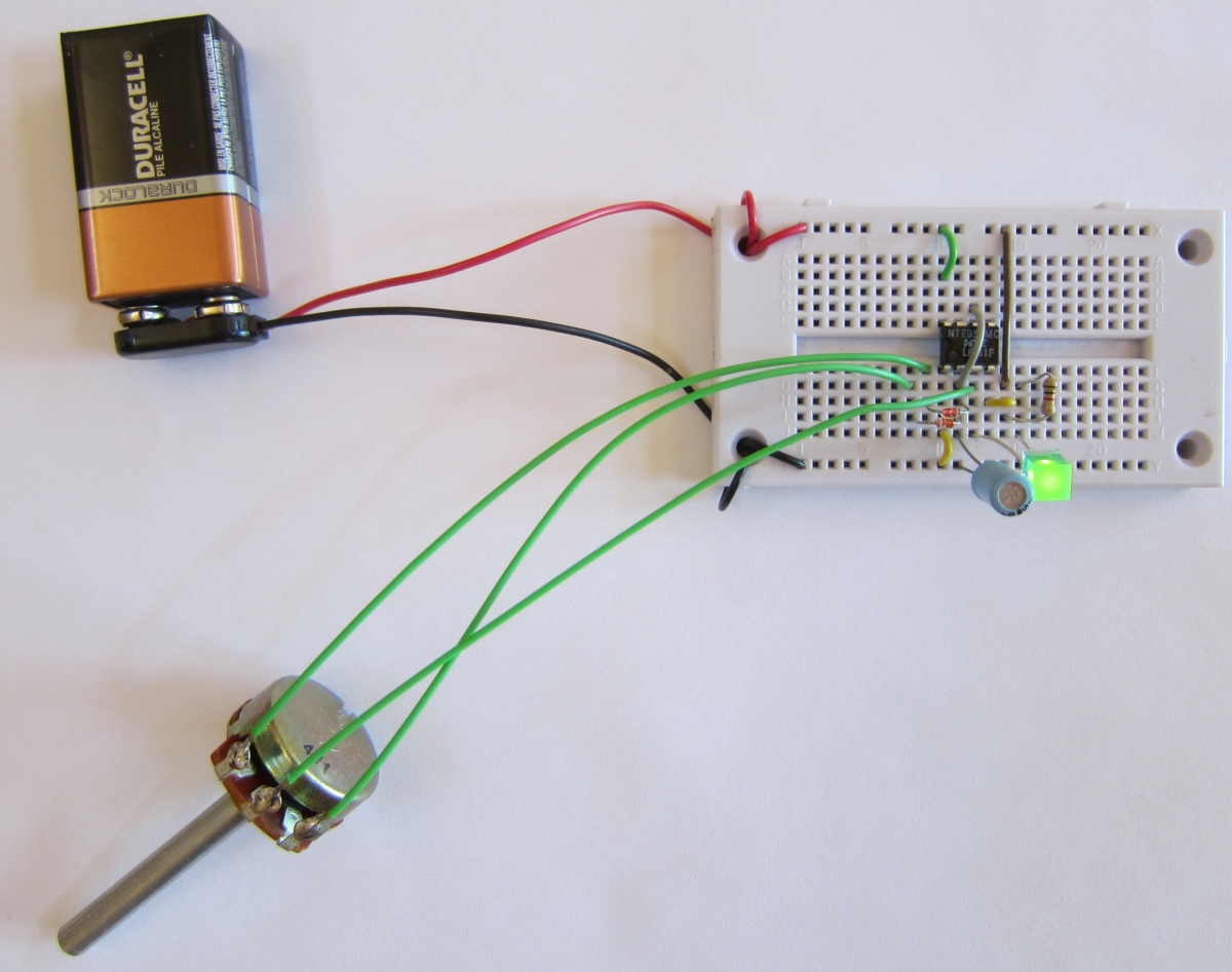
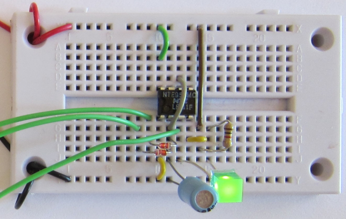
The photo above shows the circuit built on a solderless breadboard. I used a 1k ohm resistor to limit the current for the LED, but smaller values can also be used if you need more light. Below is a closeup of the same photo. You can see the white bands on the two diodes, indicating the direction of current flow. Look at each connection and match it up with the schematic diagram to convince yourself that all of the connections are actually the same, even though the layout looks completely different.