
In this project we are going to control a special type of motor called a servo motor. Servo motors are electric motors that contain electronics in them that read pulses coming in on one of their three wires. The width of those pulses controls the position of the servo motor arm. If the pulses are very short, the arm rotates counterclockwise to its limit. If the pulses get a little bit wider, the arm moves a little bit clockwise and stops. The gears in the servo mechanism allow the motor to hold its position against considerable force.
Servo motors are used in many devices, most commonly in radio controlled cars and airplanes. They are used to move flaps, ailerons, and rudders in airplanes, or to steer cars by moving the front wheels left or right.
In the schematic diagram shown above, we have modified our by now familiar PWM circuit, but with some extra resistors added.
If the pulse sent to the servo motor is 1 milliseconds long, the motor will position its rotor to the extreme left (counterclockwise) position. If the pulse is 2 milliseconds long, the rotor will more to the extreme right (clockwise) position. To center the rotor, we send a pulse that is 1.5 milliseconds long.
In between the pulses, the servo motor needs to see about 40 milliseconds of delay. If there is less than 10 milliseconds of delay, the motor will buzz and vibrate. If there is more than about 70 milliseconds, the motor will shut off in between pulses, and not hold its position.
In this circuit, we use a 0.47 microfarad capacitor. The resistance is 52,470 ohms. Our formula for the timing is
so we get a frequency of about 30 pulses per second (the pulses are separated by 33 milliseconds). In practice, since capacitors values are only about 20% accurate, and resistors about 5% accurate, we might get timings that are quite different from those we calculated. In my test circuit, the frequency was closer to 50 pulses per second (a delay of 20 milliseconds between pulses). This is why servo motors allow quite a bit of variance in the timing.
The servo pulse is very short compared to the time between pulses. This allows a transmitter to control many servos, by starting each pulse a little later on a different channel.
We don't want the resistance to go below 470 ohms, so we put a 470 ohm resistor between the potentiometer and the left diode.
Likewise, we don't want the resistance to go above about 52,000 ohms, so we add a 47K ohm resistor to the 5K ohm potentiometer's maximum resistance.
These two resistors set the limits of the left and right motion. Now the potentiometer can swing from one end to the other, and the servo motor will match that swing. So now you can twist a knob in one place, and watch something rotate in sync with it in a remote place.
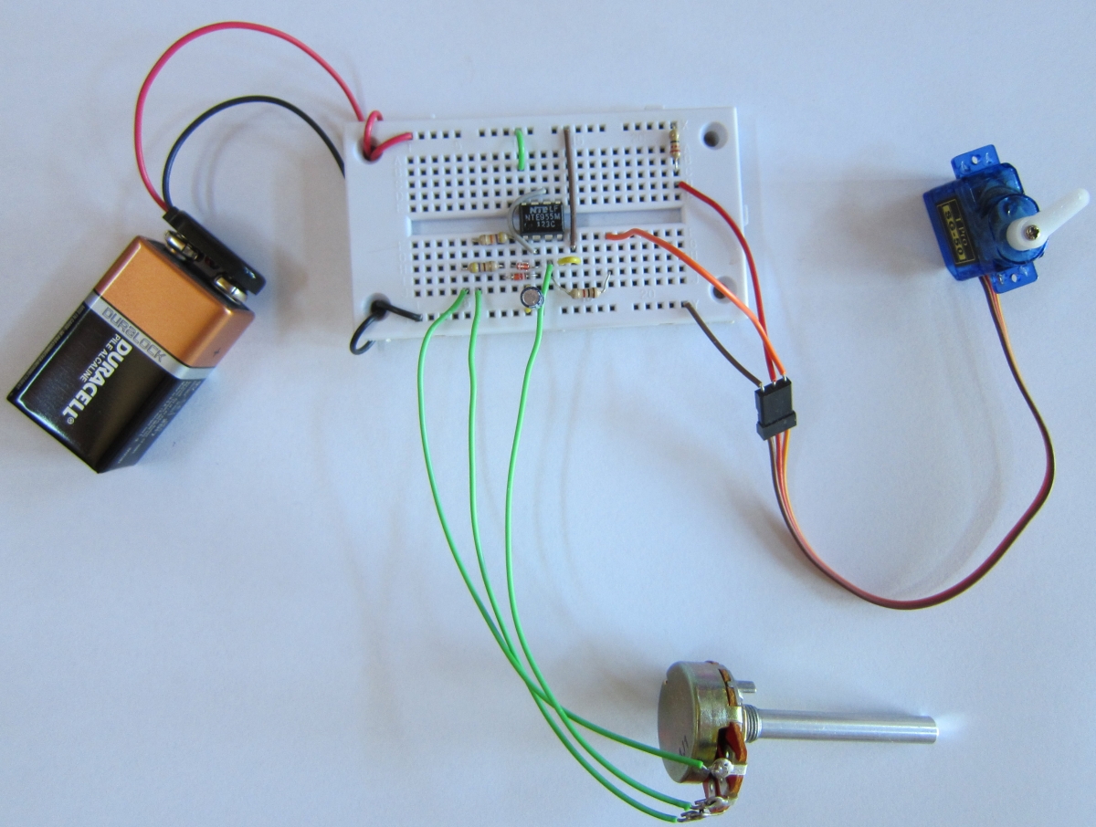
Here is what the circuit looks like when built on a solderless breadboard:
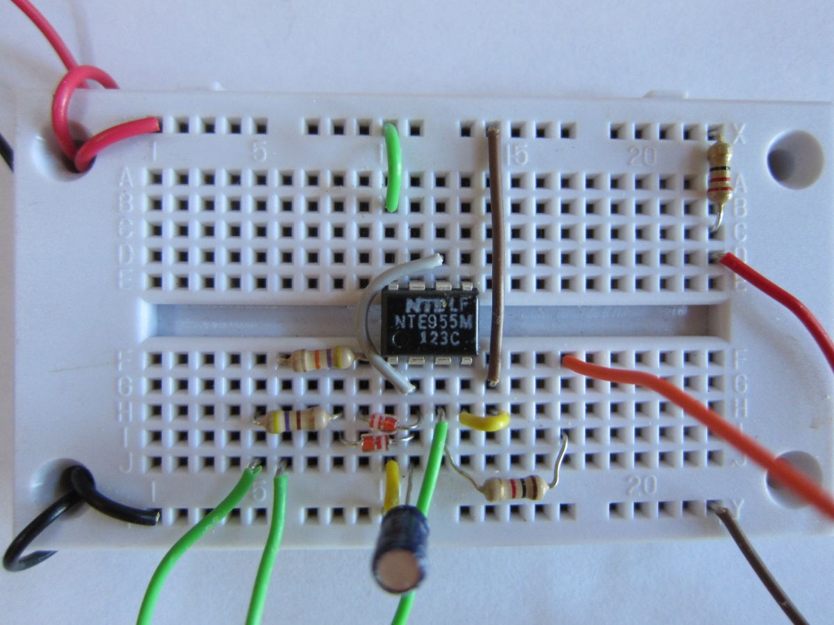
Here is the close-up view of the circuit:
Servo motors have three wires coming out of them. One is for power, the other is ground, and the last one is the control wire, which carries the pulses. The control wire does not need to carry very much current, so we can place a resistor between the output (pin 3) of the timer and the servo. This ensures that the timer operates properly, and reduces the amount of current through it in the case of a short circuit in the motor.
I have also added a 22 ohm resistor between the positive power supply and the servo. This is so the servo does not hog all of the current, so some is left for the timer chip. I could have used two batteries, one for the chip and one for the motor, to give more power to the motor. If the negative side of each battery is connected together, then all circuits connected to the batteries will have a common reference point to measure signals against. When this is done (usually connecting the grounds together) the ground is sometimes referred to as 'common'.
Connecting two power supplies using a common ground is also a way to allow the motor to run from a higher voltage than the timer chip.
Servo motor manufacturers have not decided on a standard color coding for the lead wires from the motor, or even a common arrangement for the wires in the connector. The positive wire is usually red, the ground (negative) wire is brown or black, and the control wire can be yellow, orange, black or white. You will want to check the proper wiring for whatever servo you are using.