In the previous chapter, we saw how to use a 555 timer chip to efficiently dim a light source using Pulse Width Modulation (PWM).
In this chapter we will continue exploring this method of controlling electrical power, but we will use it to control motors, make sounds, and even to create our own radio station.
It might seem obvious that if we can control the brightness of an LED then we could also control the speed of a motor using the same circuit. And it turns out we can.
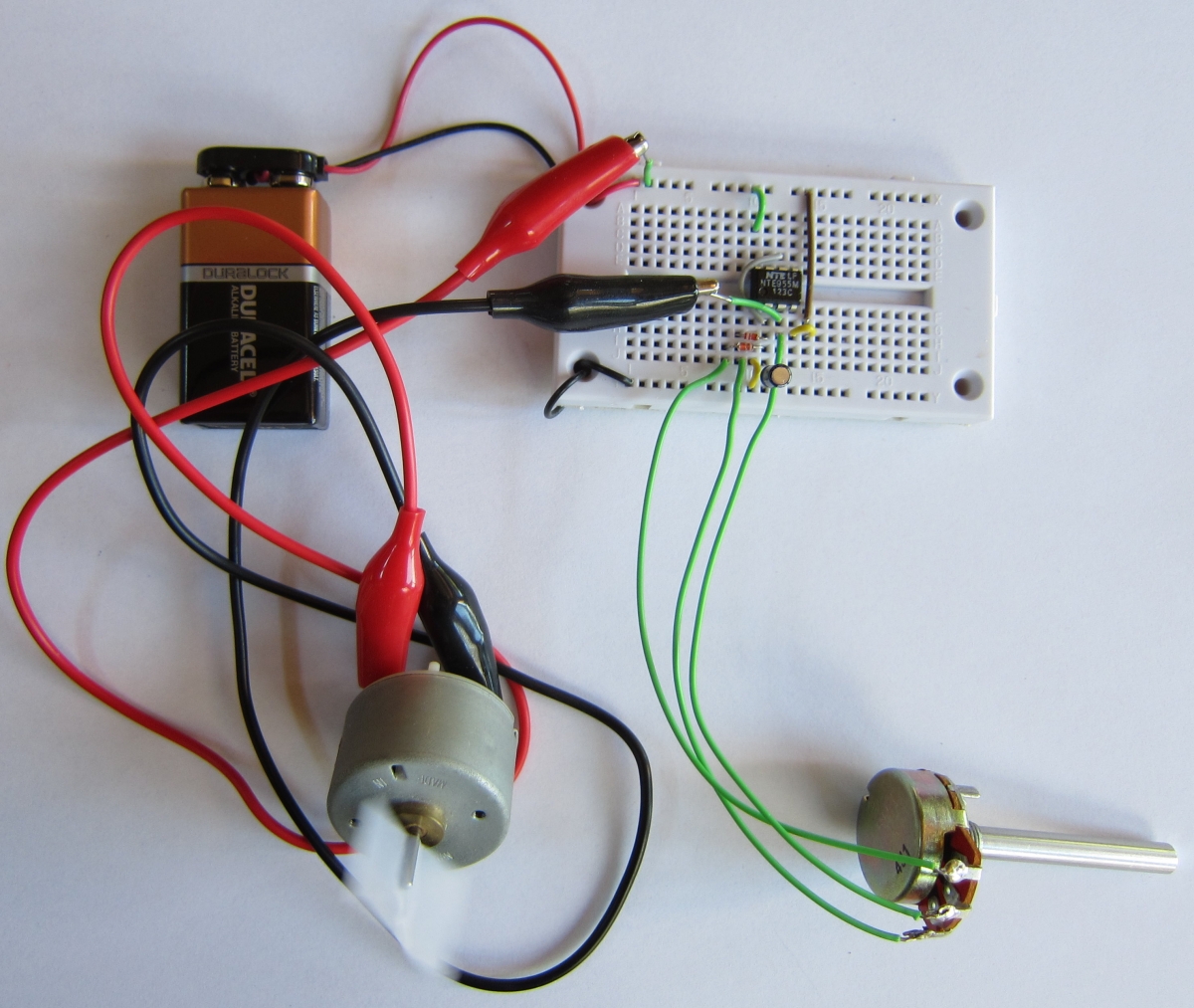
In the circuit shown above, we have replaced the LED and its resistor with plus and minus leads for a motor. We connect the positive side of the power supply directly to the motor, and the negative side of the motor connects to pin 3 of the timer. We do this because the timer can sink more current than it can source. We could have connected the motor to pin 3 and ground, but less current would be available, and the motor would not spin as fast.
Below is the circuit built on a solderless breadboard:

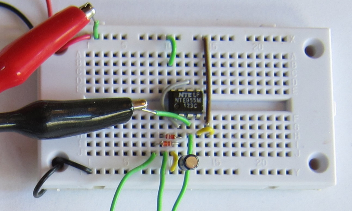
And below is a close-up view of the same circuit:

This approach to controlling a motor has some advantages over the simpler and more obvious way, which would be to use a rheostat to vary the current.
A rheostat that can handle the currents involved is a larger, more expensive device than the 555 timer and its circuit components. But also, like we saw with the pulse width modulated LED circuit, this way of controlling the motor speed ends up wasting little of the current from the battery. Using a rheostat, most of the battery current would be used heating up the rheostat, and the battery would not last long.
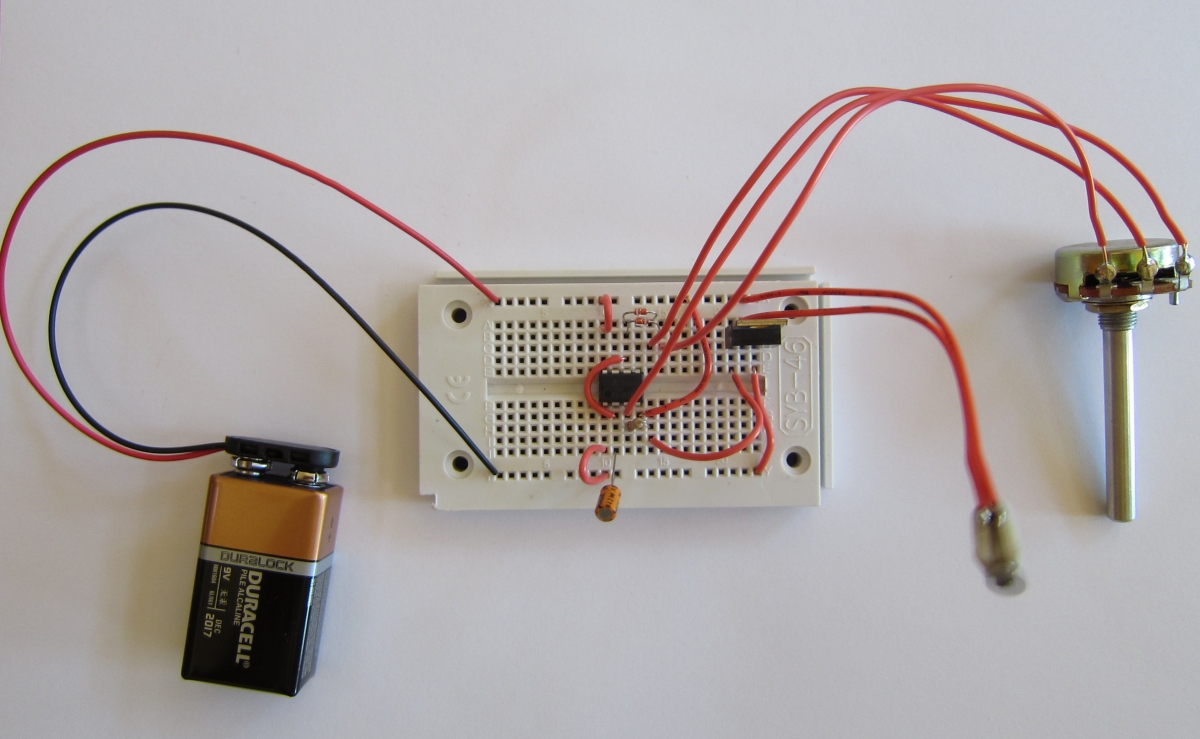
When using the 7555, we have a slight problem. The 7555 can't source or sink as much current as the 555 chip. So we need to add an NPN transistor switch to carry the current. The 7555 turns the transistor on and off by setting the base to +9 volts or ground. The transistor then switches the full power supply to the motor on and off in sync with the 7555.
In the photo below, you can see the TIP31 power transistor I used at the upper right of the breadboard. It is driving a small cellphone vibrator motor you can see as a blurry blob vibrating at the end of its connecting wires. The base of the TIP31 NPN power transistor is the left-most pin. The center pin is the collector, which is connected to the motor. The right pin is the emitter, which is connected to ground.

