
The Launchpad comes with an extra MSP430 chip, the MSP430G2452. In this project we will finally get to play with it, since we want to extend the capabilities of our Launchpad to control more LEDs.
First we will build the 14 pin PWM circuit from the Serial PWM project. We do it on a solderless breadboard as shown in the photo below:

In the photo above we have the extra chip mounted on the breadboard. We connect the Reset pin to the +3 volts of the power supply so the chip does not constantly reset itself.

When we apply 3 volts, the LEDs light up, getting successively brighter from left to right.
Notice that we have not connected anything to pins P1.1 and P1.2 yet. Those are the serial port pins. Since this chip is not mounted in the Launchpad board, we can't send serial data to it from the host computer as we have done in the past. But we can connect the serial port pins of the chip in the Launchpad to the serial port pins of the chip on the breadboard, and they can talk to one another.
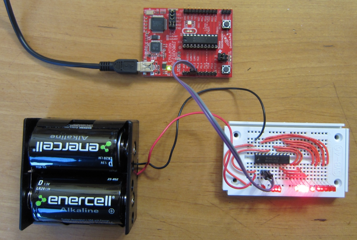
Above we can see the Launchpad connected to the breadboard circuit. P1.1 of each chip is connected to the other, as is P1.2.

The program running in the Launchpad is shown above. It tells the chip on the solderless breadboard to set the LED brightnesses to get gradually larger and then smaller again. Then it makes the peak brightness move back and forth along the 14 LEDs, as if it were the scanning sensors on a Cylon robot, or Kitt the TransAm on an old television show.
To program the extra chip (the MSP430g2452), we first carefully remove the MSP430g2553 chip from the Launchpad. The chip is sensitive to static electricity, so we want to touch something that is grounded to get rid of any charge on our hands before touching the pins. Then we place the chip on something conductive, such as a sheet of aluminum foil to protect it from static electricity. Wearing cotton or wool clothing instead of nylon or polyester will also help reduce static electricity.
The pins on the extra chip may need to be straightened before they will fit into the socket. Many chips come from the factory with the pins splayed out just a little bit.
Once the new chip is inserted into the socket, you will need to remember to change the Tools|Board menu to let Energia know we are using the MSP430g2452 chip instead of the MSP430g2553 chip that was originally in the socket.
Note: If you want to test the chip by sending serial data to it, you will also need to change the TXD and RXD jumpers on the Launchpad from the hardware UART setting to the software UART setting, since the extra chip does not have a hardware UART (Universal Asynchronous Receiver Transmitter -- i.e. serial port). But that step is not necessary if we aren't testing the new program from the host computer.
The next step is to program the chip with the Serial PWM code.
Then we disconnect the power and remove the chip from the Launchpad and place it in the solderless breadboard.
We now put the original MSP430g2553 chip into the Launchpad, set the Tools|Board menu back to MSP430g2553, and load the program to send serial data to the chip in the breadboard.
When we connect the two chips' serial pins together and power everything up, we get a scanning LED pattern moving on the breadboard. The chip in the Launchpad has outsourced the work of doing the Pulse Width Modulation to the chip in the breadboard. Now the Launchpad is free to spend its time doing other things, and it has 14 pins free to use for inputs and outputs.
We can connect several of the circuits together, using four wires (power, ground, serial in, and serial out) as shown in the photo below:
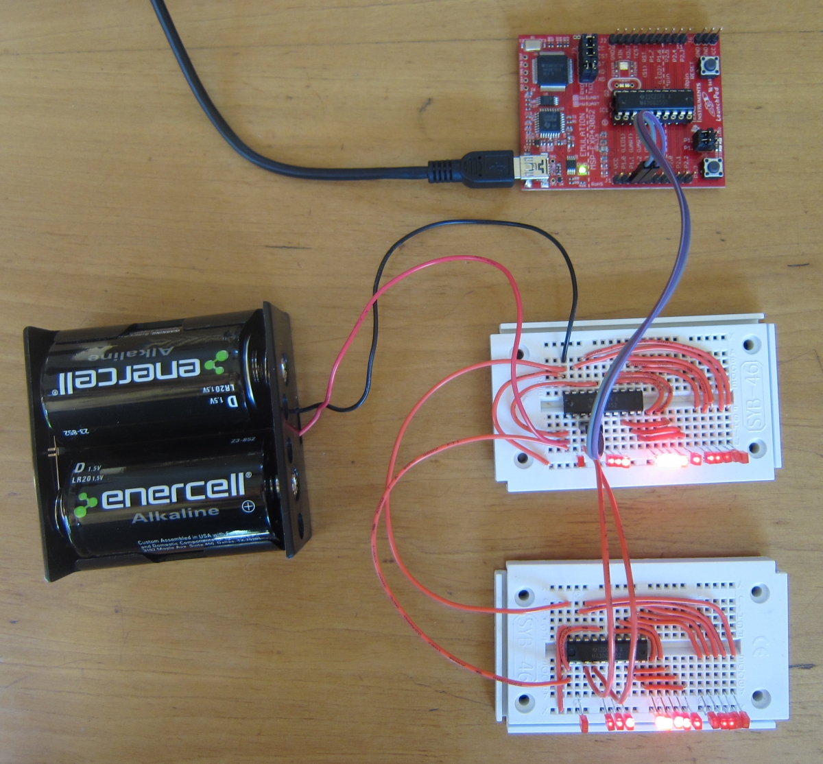
Both of the solderless breadboards are lighting their LEDs in sync, controlled by the Launchpad.
Controlling the extra chips this way means that we can change what all of the 'slave' chips do, just by changing the one program in the Launchpad. We don't have to keep unplugging and plugging in chips when we want to make a change.
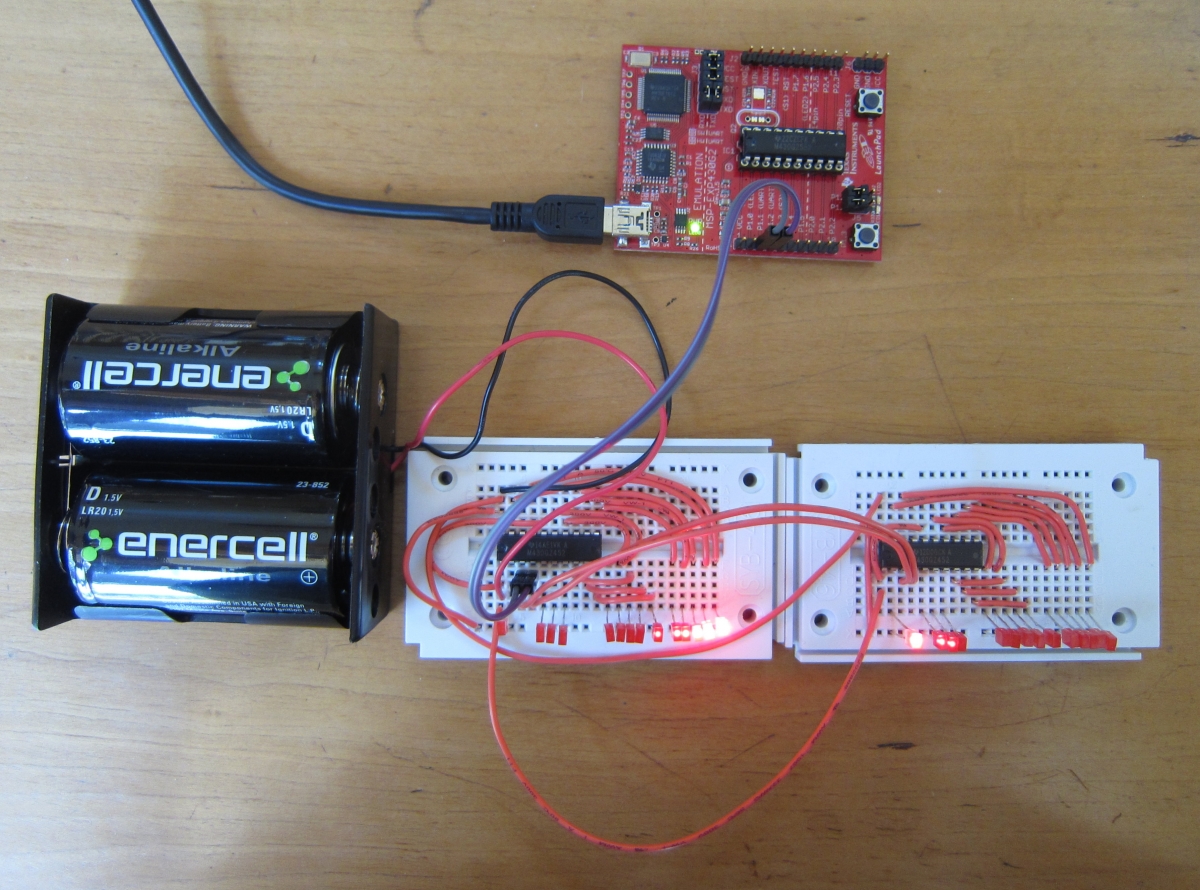
We can take things one step farther, and make it so we can control 16 of the extra chips individually. To do this, we give each one an address. This is just an extra digit in the sequence we send the chip. Each chip is programmed with a number from 0 to 15, which is its address. We send the address as the first character of the sequence. If the chip sees that the address it not its own, it simply ignores the command sequence.
The program for the slave chip is here. The program for the master chip is here.
As the photo below shows, now the two slave chips are not merely mimicking one another in lock step. We have turned our 14 LED Cylon into a 28 LED Cylon.
With 16 slave chips controlling 14 LEDs each, one master Launchpad can control the brightness of as many as 224 individual LEDs. And if you need more, you can just add another digit of address, to control 3,584 LEDs.
Having lots of PWM pins comes in very handy when you want to control the color of a lot of RGB LEDs. Each RGB LED has a red, green, and a blue LED inside the plastic lens, so it has four leads. It thus takes three pins to control the color (and brightness). One chip can control only four or five of these LEDs at a time before running out of pins. But with a slave chip, we have 28 pins available, so we can control 9 RGB LEDs, and still have one pin left over.
You may have noticed that we are only using two wires (transmit and receive) to communicate between the various computers. How can they agree on what zero volts means if they do not share a common ground connection? As it turns out, for short connections like this, the computers agree on a common ground whenever the lines are in the LOW state. For longer wires, the capacitance of the wire would delay this agreement by enough to cause problems, and we would need to connect the grounds of the computers with another wire. But for short connections, this works.