
The serial port, and the Serial class that manages it, deal with asynchronous communication. This just means that there is no shared clock in the two computers. Each computer has its own clock, and each expects the bits to have an agreed-upon duration. This means the computers need to agree on how fast the bits are sent. If one computer is sending data at 9600 bits per second, and the other is expecting them to come in at 1200 bits per second, they will not be able to communicate.
Synchronous communication uses another wire to send pulses that act as a clock. This means that the two computers no longer need to agree ahead of time on the speed of the communication, and thus the duration of the bits. The clock pulses tell the receiver when to look at the state of the pin receiving the bits.
The Launchpad has hardware that makes it easy to use a form of synchronous communication called SPI, which is short for Serial Peripheral Interface. This method is used by many devices that need to communicate with the microprocessor, such as temperature sensors, barometric sensors, digital potentiometers (volume controls), radio interfaces, switches, and other input or output devices.
In the previous example of a serially controlled Pulse Width Modulator for LEDs, we had each slave device programmed with its own address, and we sent the address as part of the serial data. SPI uses another wire to do the addressing. Each SPI slave device has a pin it can read to see if it has been addressed. The host SPI device sets a pin high to tell the slave it should listen to the data. In this way the host can communicate to as many slaves as there are spare pins to address them. And each slave can run the same software, since they don't need to be programmed with their own address.
So the SPI interface has four wires between the two devices. There is the clock (called SCLK), the Master Out Slave In (MOSI), which is how the master talks to the slave, the Master In Slave Out (MISO), which is how the slave talks to the master, and the Slave Select line (SS), which tells the slave to listen.
Each slave shares the first three lines. Only one slave at a time is selected.
On the Launchpad, SCLK is always pin P1_5. MOSI is always pin P1_7, and MISO is always pin P1_6. We get to choose which pine we use for the Chip Select (CS) function.
One big advantage we get from using a synchronous protocol is speed. Few asynchronous devices can reach a million bits per second, and the Launchpad serial is limited to 9600 bits per second when talking to the host computer. But the SPI clock can run at 8,000,000 bits per second.
We don't always need that speed, so we use ordinary serial communications more often, as they use fewer pins. But fast communication comes in handy when we want to read external memory, such as the SDHC cards used in digital cameras. These cards can talk to the Launchpad using SPI.

The photo above shows an SDHC card reader. The card slips into the large metal socket on the right. On the left we can see seven pairs of pins. We will only use six pins, since the card reader can run on either 5 volts or 3.3 volts, and we only need the 3.3 volt pin. The second row of pins is not needed.
As you can see in the photo, the pins are labelled GND (ground), 5V, 3.3V, CS (Chip Select), MOSI, SCK, and MISO. All we need to do is connect those pins to their counterparts on the Launchpad.
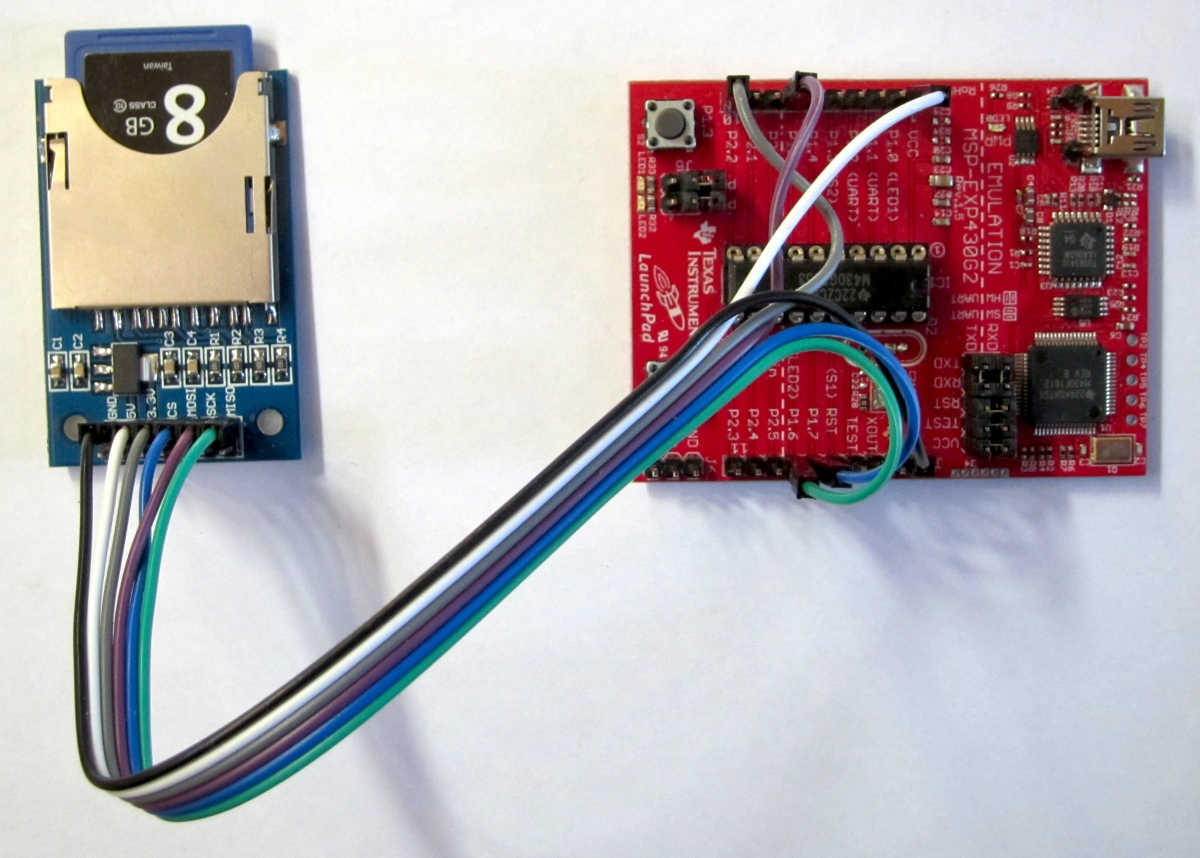
In this project, we will connect the pins using a six strand ribbon cable with female sockets at each end. Follow the wires in the photo to see how each labelled pin on the card reader is matched to the appropriate pin on the Launchpad.
Dealing with all the complexities of reading files on the SDHC card is made easier by a library of routines we can load onto the Launchpad. The version of this library that I used is in the file pfatfs.zip, and you can download it if you like, but the latest version can be found here, (http://forum.43oh.com/topic/3209-energia-library-petit-fatfs-sd-card-library/) along with support from the people who wrote it.
When you installed Energia, a tree of folders were created on your computer. On my computer, the tree looks like this:
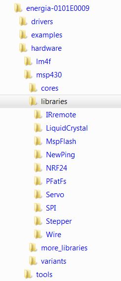
To install the pfatfs library, you want to unzip the file into the energia/hardware/msp430/libraries folder. It will then sit amoung your other libraries such as Servo and Stepper, and we can use it the same way we use them. On your machine, the energia directory is named whatever you called it when you installed Energia. If you have forgotten where it is, search your computer for Servo, or Stepper, and you will find it.
The program below reads a file from the SD card and sends the data to a speaker using analogWrite():

The first things we do are include the header files for the SPI and pfatfs libraries. The parts of the program that deal with the SD card are the FatFs class methods begin(), open(), and read().
We tell the begin() method which pin we have chosen to use as the Chip Select signal. We tell the open() method the name of the file we wish to open. We tell the read() method where to put the data, how much to read, and the address of a variable that will return how much was actually read (we may be near the end of the file).
That's how simple it is.
Almost.
There are some limitations on what we can do with the SD card. To keep the library small enough to fit on the Launchpad, some limitations were introduced. File names cannot be longer than 8 characters. We can overwrite bytes in a file, but we cannot create new files, or make files longer.
To finish up this project, let's put a file on the SD card. The file I chose is a raw sound file, consisting of just a sequence of unsigned bytes. Most sound editing programs have the ability to output the sounds in raw format. In this case, the file is Leonard Nimoy's voice as Science Officer Spock, recording a message on his answering machine. The MP3 version of the file you can actually listen to right now is here, The raw version that we want to put on the SD card is here. Right mouse on that last link and select "Save as..." to download the file onto your computer.
To hear the message from Spock, we need a speaker. I have chosen to amplify the speaker using a TIP31 transistor.

The left leg of the transistor is the base. It will be connected to pin P2_1 on the Launchpad. The center pin is the collector. It is soldered to one of the speaker leads. The right pin is the emitter. It connects to ground on the Launchpad. Finally, we connect the other speaker lead to Vcc (3.3 volts) on the Launchpad. Using a transistor gets us plenty of volume out of our speaker.
Lastly, to make it portable, I soldered pins to the TP1 and TP3 holes next to the USB cable, so I can plug in a battery pack to give us nearly 5 volts.

Now every time you push the Reset button or power up the Launchpad, you hear Spock's answering machine message.
We are no longer limited by the small amount of flash memory on the Launchpad when it comes to storing voice data. Where before we were limited to a little over a second of sound, now we can store days and days worth.