
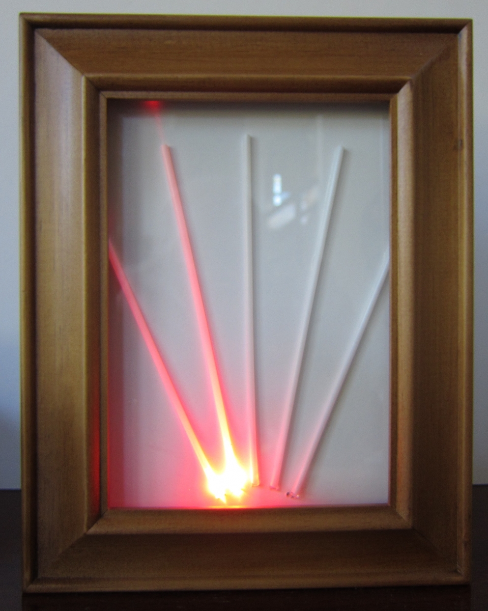
In this project, we will build a metronome out of LEDs, soda straws, a tiny speaker, and our Launchpad computer.
The LEDs in this case are small 3 (millimeter diameter), and so we use straws that are also narrow, and just barely fit over the LED. The white plastic straw guides the light, and glows like a red wand. In this way we can simulate the pendulum of the metronome by sequentially turning the LEDs on one after another so they appear to wave back and forth. At each end of the wave, the speaker gives a little click, to count the time.
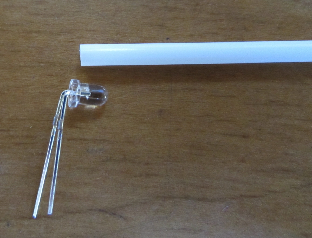
We start with the LED and the straw. We bend the legs of the LED at a right angle.
To hold the LEDs and the straws in the right places, we mount them on a bit of foam-core board. The legs of the LED can simply be pushed through the board, and the straw is pushed onto the LED.
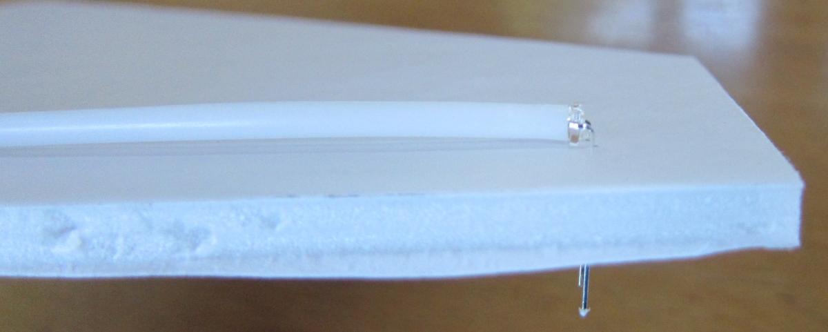
A dab of glue holds the straw in place. The leads of the five LEDs are bent on the back of the foam-core board. The long leads are all soldered together. They will connect to the ground pin on the computer. Each of the other leads is given a wire that leads to one of the output pins of the computer.
We put the foam-core behind the glass of a small picture frame, and attach the battery holder and the computer using double-stick tape.
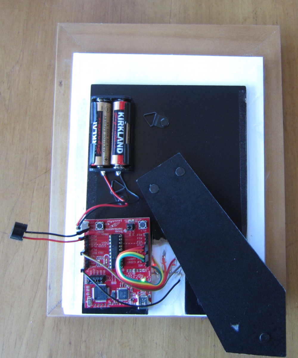
The speaker is the little black cylinder connected to pin P2_3 and one of the ground pins. The VCC pin and the other ground pin are connected to the battery. (VCC is the computer term for the positive side of the power supply.)
The program for the metronome is here.
The main complexity in the code is the way we set the speed of the metronome. We use the second pushbutton (the first one is hard-connected to the computer's reset pin, so we can't use it). Tapping the button like a drum is how you set the metronome speed. We wait for 8 taps of the button, and save the time between the taps in memory. We throw out the first one, since people usually take a second to get the timing right when they start drumming.
Using the average time between taps, we then use that as the time between clicks on the metronome.
We make the clicks by simply sending a 1 bit to the speaker for a millisecond.
The LEDs are connected to unused pins on PORT1. Pins 0 and 6 are used for the on-board LEDs, which we use to give the user feedback when setting the timing. Pin 3 is connected to the pushbutton. That leaves P1.1, P1.2, P1.4, P1.5, and P1.7 available for the LEDs of the pendulum. Since they are not all contiguous, we don't use fancy bit twiddling tricks, we simply have an array of values to send to PORT1.