
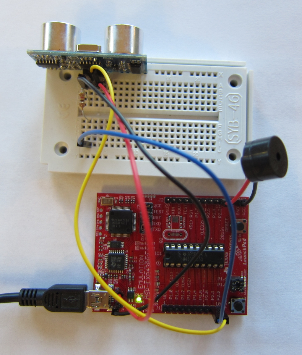
The photo above shows a sonar sensor called the HC-SR04 plugged into a solderless breadboard.
The sonar sensor sends out a pulse of ultrasound, well above the hearing range of people and animals. When it hears the echo, it brings one of its pin from ground to +5 volts, for a period that corresponds to how long it took the echo to come back.
Since the HC-SR04 is designed to run at 5 volts, we can't simply power it from the Launchpad's 3.3 volt power supply. We have to find 5 volts somewhere.
We could simply use a second power supply, and connect the grounds together so the computer and the HC-SR04 both agree on what the zero volt level is. But it just so happens that the Launchpad gets 5 volts from the USB port of the computer it is attached to, and there is a hole in the circuit board we can solder a wire to that is connected to that 5 volts.
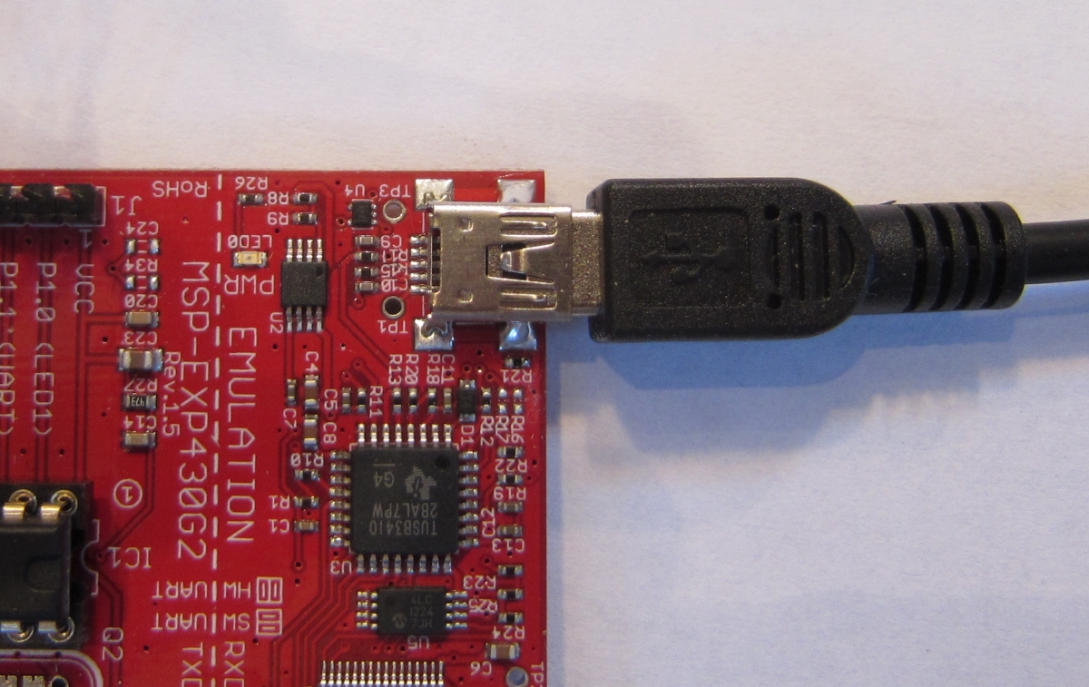
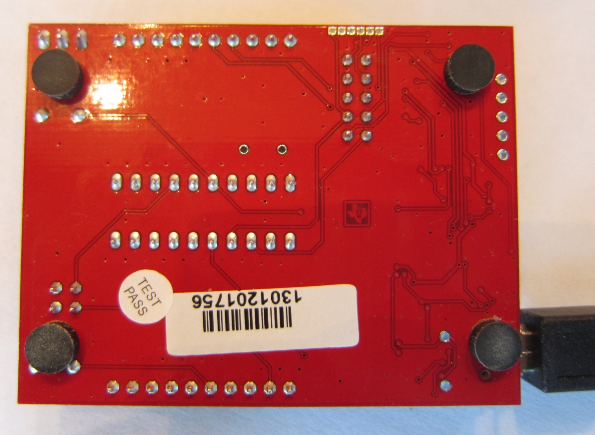
The hole in the circuit board is labeled TP1 (that stands for Test Point 1). It is easy to insert a wire into the hole and solder it in place on the back side of the board, because there is almost nothing you can damage or mess up on that side. Even a novice at soldering can safely solder a wire there.
In the photo above you can see the two holes next to the USB connector at the bottom right, The upper of the two holes is TP1.
The HC-SR04 puts out 5 volt signals, which the Launchpad can't read. We need to drop the voltage down to between 1 and 3.3 volts. The simplest way to do this is to limit the current with a 1,000 ohm resistor. Because there is less current, the voltage will drop to something the Launchpad can handle.
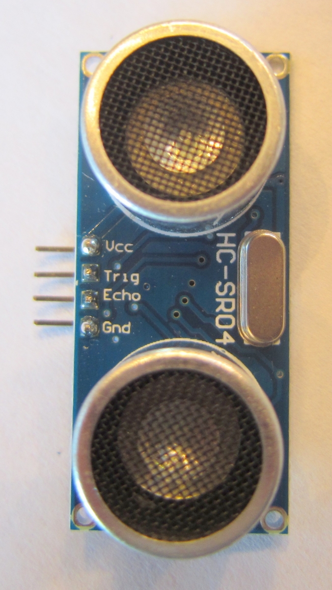
The HC-SR04 has four pins. We connect +5 volts to the pin labeled Vcc. We connect the pin labeled Gnd to ground. The Echo pin is the output that needs to have the 1,000 ohm resistor. The other side of that resistor goes to an input pin. In our example program, that will be Port 2 pin 1.
The remaining pin is the Trig pin. Setting that pin high tells the device to send out a pulse of ultrasound. The Launchpad can raise this pin to 3.3 volts, which is short of the 5 volts that the HC-SR04 expects, but is high enough to be accepted as a HIGH signal.
In our example program, the setup() function starts the serial port after a 5 second delay to allow us to bring up the Serial Monitor window. It then prints a startup message, and sets up the port pins.
In the loop() function, we get the average distance the sonar sensor sees in front of it, and print that out. Then we send out a beep to a speaker connected to Port 2 pin 3. The frequency of the tone corresponds to the distance between the sensor and what it is sensing.
We wrote our own beep() function, because the tone() function supplied in the standard library uses a timer that is also used by pulseIn(), and we will need to use the pulseIn() function to read the sonar sensor.
The get_distance() function is what does the sonar sensor reading. It sends out a 5 microsecond pulse to the sensor's Trig pin to tell the sensor to send out a sonar pulse. Then we time the resulting signal from the Echo pin using pulseIn(), which returns the length of the pulse in microseconds. We convert that time to centimeters by dividing by twice the speed of sound in microseconds per centimeter (which works out to be 58.77).
As we did with the LED proximity sensor, we filter the results by sorting samples and averaging those near the median.
As you move your hand towards the sensor, the pitch of the beeps rises. As you move away, the pitch falls.